Mechanical microscopy is a flexible technology that allows numerous nanoindentation techniques to provide various imaging modalities to investigate the spatial distribution of different mechanical properties. Using strain rate jump nanoindentation, the strain rate sensitivity of different phases within a microstructure can be directly mapped in a rapid manner. In this application note, we demonstrate the use of high-speed strain rate jump nanoindentation mapping to perform mechanical microscopy of strain rate sensitivity on a Fe-Cu4%Sn laminate material. This illustrates the potential of this technique for mapping the rate sensitivity of microstructural features in a high-throughput manner.
Introduction
Mechanical microscopy is more than nanoindentation hardness and modulus mapping. Nanoindentation is a powerful technique that allows the characterization of a wide range of mechanical properties. Many of these indentation techniques and mechanical properties are also suitable for mapping, enabling new imaging modalities for mechanical microscopy. One of these indentation techniques is strain rate jump (SRJ) testing, which dynamically varies the indentation strain rate during an individual indentation to characterize the strain rate sensitivity of a volume. This technique and indentation strain rate is described in detail in another Oxford Instruments application note titled, “Strain and Nanoindentation.”
In this application note, we describe a new mechanical microscopy imaging modality to map strain rate sensitivity using strain rate jump nanoindentation mapping. We apply SRJ mapping to demonstrate mechanical microscopy of strain rate sensitivity variations across a laminate of Fe and CuSn4.
Experimental Considerations
To perform this application, several system features are required. Displacement control is important, as it has the most direct relationship to strain rate control, and it ensures consistent indentation depths during mapping of phases with different hardness levels. Continuous stiffness measurement (CSM) is required in order to provide hardness measurements as a function of depth and strain rate.
Displacement Control
For mapping strain rate sensitivity, displacement control is beneficial in two ways: strain rate control and consistent indentation size. The indentation strain rate is a direct function of the displacement rate divided by the current displacement:
 This means that displacement control is the ideal control mode for testing with controlled strain rates.
To ensure consistent sampling size during mechanical microscopy, indentations should all be performed to the same depth. In load control, the load must be carefully chosen to ensure that the spacing is proportional to the indentation produced in the softest phase in the map. Otherwise, indentations in the soft region will overlap with its neighbors. In addition, at a fixed indentation load, indentation sizes scale with the hardness of the material, resulting in inconsistent sampling size. In displacement control, indentations are all performed to the same maximum depth, ensuring similar indentation sizes and regular with minor variations from differences in elastic recovery.
Continuous Stiffness Measurement
Continuous stiffness measurements allow the acquisition of numerous stiffness datapoints to be acquired as a function of penetration depth during a single indentation. This allows hardness and reduced modulus to be measured as a function of depth during indentation. This is required for SRJ mapping, in which the variation of hardness vs strain rate must be measured during the indentation process.
Sample Production
The laminates were manufactured using accumulative roll-bonding (ARB) by Prof. Göken’s group at Friedrich-Alexander-Universität Erlangen-Nürnberg (FAU). Wieland® and Armco® iron sheets with a purity of 99.85% were used. Fe and CuSn4 (phosphor bronze) were chosen because of their similar strength in cold-worked condition, which assists in achieving good bonding and uniform deformation during roll-bonding. The sheets were cut into 125×300×1 mm pieces. Prior to roll-bonding, the surfaces of the two sheets were degreased and cleaned with acetone and then wire-brushed to remove any oxide layer and ensure a reproducible surface roughness and sufficient bond strength. Subsequently, the treated surfaces were stacked on top of each other and roll-bonded at room temperature using a four high rolling mill (BW200, Carl Wezel, Muehlacker, Germany) with a roll diameter of 90 mm and a rolling speed of 8 m min-1 at a nominal thickness reduction of 50% per cycle. Each rolling cycle was followed by an annealing treatment at 400 °C for 30 min to reduce the difference in strength between the two materials. The sheets were air cooled and then halved before performing the next ARB cycle. The edge regions of the rolled sheets, where tearing and crack formation typically occur, were cut away and only the central part with good bonding quality was used for the following ARB cycles.
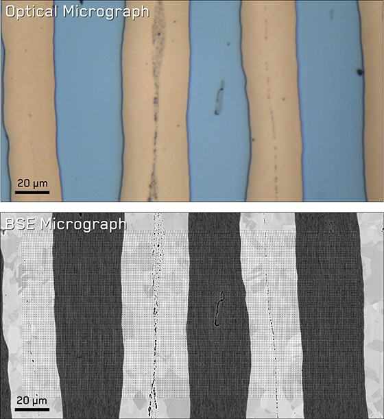 Figure 1. Optical and SEM micrograph of the Fe/CuSn4 laminate.
The sheets were stacked so that CuSn4 is bonded with Fe to achieve alternating layers of CuSn4 and Fe. However, initially, Fe sheets and CuSn4 sheets were bonded together to themselves to achieve a desired thickness, then alternating layers were bonded. Samples were metallographically prepared in the rolling-normal direction plane. Optical microscopy (Figure 1) reveals that good bonding was achieved with fairly uniform layer thicknesses. Some oxidation did occur during annealing cycles, as can be seen as darker, porous regions in the middle of the layers.
Indentation Procedures
A nanoindentation map of 128×72 strain rate jump indents were performed on each sample using an NMT04 In-Situ SEM Nanoindenter with a diamond Berkovich indenter on a FT-S20,000 sensor. Testing was performed in situ in a Zeiss EVO 25 scanning electron microscope (SEM) operating at an acceleration voltage of 10 kV. Each indentation was performed to a maximum depth of 190 nm using a continuous stiffness measurement (CSM) method [1] in strain rate control. The indentations were performed with an oscillation frequency of 200 Hz and an amplitude that linearly increased from 0.5 to 3 nm with increasing depth. A high oscillation frequency is required for this application to enable measurements at higher indentation strain rates.
Each indentation was performed to a specified depth of 190 nm, so that a spacing of 2 µm between indentations could be used while still ensuring an indentation depth/spacing ratio of 10 was maintained [3]. This avoids any significant interaction between neighboring indents.
Indentation strain rate jump tests were performed using a method similar to that of Maier et al. [2], where the strain rate is abruptly varied during indentation to several different levels. During each indentation, the strain rate was initially held constant at 2 s-1 until a depth of 80 nm was reached, then the rate was dropped to 0.02 s-1 until 100 nm, and then back to 2 s-1 until the maximum indentation depth of 190 nm. These rates and the lengths of the jump segments were optimized to reduce total indentation time such that each indentation including repositioning time was performed in 9.2 s.
Results and Discussion
Indentation Curves
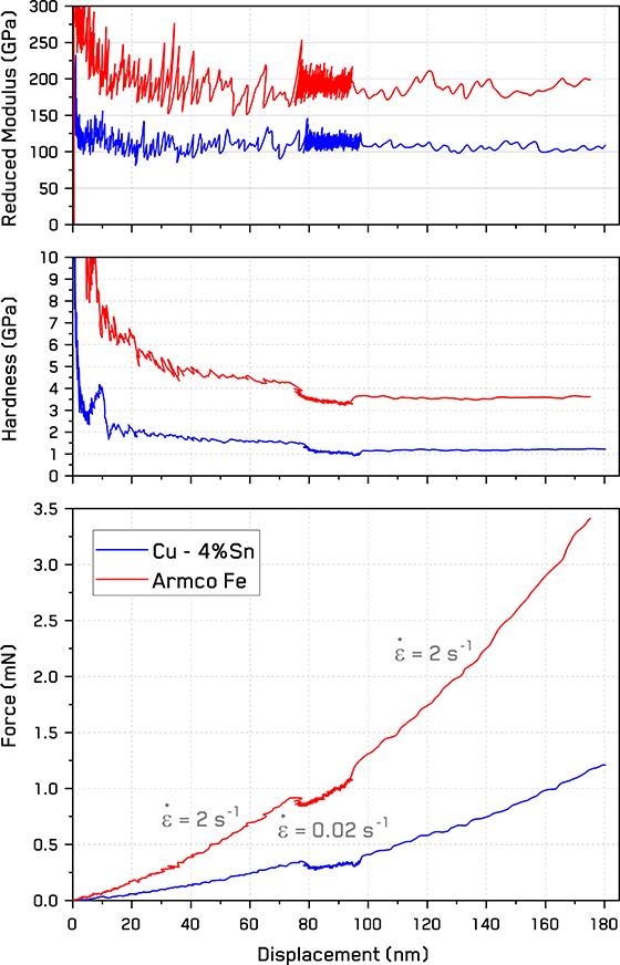
Figure 2. Exemplar force, hardness, and reduced modulus vs displacement curves for both phases in the laminate.
For each strain rate jump indentation, the complete dataset is retained and available for analysis. To generate the property maps shown in Figure 2, representative values were extracted from the force-, hardness-, and reduced modulus-displacement curves. Hardness and reduced modulus values for the maps are taken from the average of the last 50% of the displacement.
For the strain rate sensitivity map, force and hardness are seen to decrease during the reduced strain rate jump segment between ~80-100 nm, which indicates positive rate sensitivity. As seen in the previous application note in strain rate jump testing, reduced modulus in Figure 2 is independent of strain rate. Small variation in the position of the jump segment is seen with harder samples due to correction of the displacement for system compliance. Values from the jump segments were taken from 15 nm wide segments were averaged from before, during, and after the 0.02 s-1 jump segment.
From the variation in hardness with strain rate between the jump segments in each indentation (Figure 2), the strain rate sensitivity, m, can be determined using the following relationship [2, 3]:
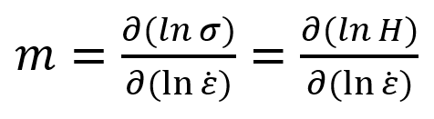
which results from the equation above using the Tabor confinement parameter, the Berkovich hardness value is related to the equivalent flow stress, σf, at 7% representative strain (eBerkovich = 7%) by the relationship, σf = H/2.8 [2].
However, as there is a noticeable indentation size effect in many of the indentation curves, this must be subtracted in order to determine the true variation in stress vs. strain rate. This could be done by fitting a relationship and subtracting it from the data. However, given the large volume of data generated during mapping, a numerically simpler approach is beneficial. As the strain rate is jumped down and then back up, the variation in hardness between these two rates can be summarized by difference between the average of two segments before and after the rate jump and the segment during the rate jump. This effectively corrects for any hardness variation with depth and averages out any local variations due to intermittent plastic flow.
Property Maps
Figure 3 shows the hardness, reduced modulus, and strain rate sensitivity maps obtained on the Fe/CuSn4 laminate sample. The Fe layers are clearly visible as the four harder vertical stripes. As mentioned in §2.3, each of these stripes consists of two bonded Fe layers, but the Fe-Fe interfaces are clean and not visible in these maps. An Fe oxide defect in between Fe layers can be seen in the other region shown in Figure 1. The CuSn4 layers in the maps, however, show evidence of a harder Cu oxide phase between CuSn4-CuSn4 layers. The Fe-CuSn4 interfaces appear strong and well-bonded with no evidence of cracks or porosity.
The reduced modulus map shows very similar morphology to the hardness map. The porous Cu oxide phase shows lower modulus values than the surrounding CuSn4. In general the reduced modulus values are fairly uniform without significant grain contrast within the phases.
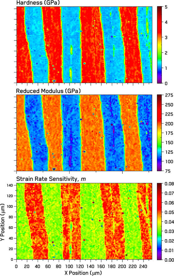
Figure 3. Hardness, reduced modulus, and strain rate sensitivity maps of the Fe and CuSn4 laminate.
The strain rate sensitivity map shows an inverse correlation with the hardness maps, with the exception of the Cu oxide phase. Greater local variation is observed in the strain rate sensitivity map than in hardness or reduced modulus, which may indicate greater sensitivity to grain orientations. The sensitivity of the SRS measurements can be enhanced by imposing a larger jump in strain rate, but this would decrease the mapping speed.
Phase Properties
As the Fe and CuSn4 phases are show quite distinct properties, their phase level properties can be easily segmented from the maps using cluster analysis with a mixed Gaussian distribution fit. This was performed using three clusters in order to have two major clusters for the two main phases and one cluster for outlier indentations falling on the oxide phase and on phase boundaries. Only the main phases are analyzed further. The extracted mechanical property values are summarized in Table 1.
Hardness values reveal the Fe phase to be ~3× harder than the CuSn4 bronze phase. This reflects the effectiveness of the annealing cycles to recrystallize the CuSn4 due to its lower melting point. Values for each phase are quite consistent, as reflected by the uniformity of their appearance in the map in Figure 3 and the low standard deviations in Table 1.
To discuss elastic modulus values, the effect of Poisson’s ratio, ν, on measurements must first be mentioned. The measured reduced modulus during indentation maps are not corrected for Poisson’s ratio, since this is not known for each phase prior to mapping. After phase segmentation, if the Poisson’s ratio for each phase is known, it is possible to correct the elastic modulus using the reduced modulus equation [7,8]:
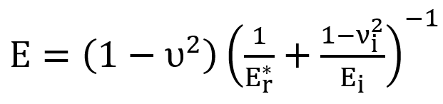 where E is the Young’s modulus of the material, is the reduced modulus, and ν and νi are the Poisson’s ratio of the sample and the indenter tip material (Diamond - Ei = 1120 GPa, νi = 0.07), respectively. Using the Poisson’s ratios for each phase, we determined the Young’s modulus of each phase from the measured values - Table 1. Young’s moduli values for the Fe and CuSn4 phases are in agreement with literature values: ECuSn4 = 111 GPa [4] and EFe = 213 GPa [5].
Strain rate sensitivity values, like hardness values, are a function of the processing and microstructure of the material, so they do not have reference values like Young’s modulus. To interpret the strain rate sensitivity values, it is useful to convert them into apparent activation volumes, V. These provide a “fingerprint” for the deformation mechanism’s time-dependence. This is done using the following relation:
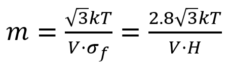 where k is the Boltzmann constant, T is the absolute temperature, σf is the equivalent flow stress, H is the hardness, and V is the apparent activation volume for the plastic deformation.
The activation volume is often discussed in terms of the thermally-activated motion of dislocations with different dislocation mechanisms being associated with different ranges of values over several orders of magnitude of volume [6], which is scaled in terms of cubic Burger’s vectors, b3. The activation volumes measured for each phase in the laminate (VCu = 20.1 b3 and VFe = 12.0 b3) show values (10-20 b3) associated with dislocation glide [6], which is consistent the deformation of fine-grained metals.
Table 1. Mechanical properties of individual phases measured from the Fe/CuSn4 laminate using SRJ nanoindentation mapping. Values of Poisson’s ratio and strain rate sensitivity are dimensionless.
|
Phase
|
N
|
Hardness
(GPa)
|
Elastic Properties (GPa)
|
Strain Rate Sensitivity
|
Activation Volume
(b3)
|
|
EReduced
|
ν
|
E
|
|
Mean
|
SD
|
Mean
|
SD
|
-
|
Mean
|
Mean
|
SD
|
Mean
|
SD
|
|
Fe
|
4405
|
3.28
|
0.15
|
194.3
|
4.6
|
0.3
|
212.9
|
0.033
|
0.004
|
12.0
|
1.7
|
|
CuSn4
|
4055
|
1.20
|
0.08
|
114.6
|
4.8
|
0.34
|
112.6
|
0.050
|
0.004
|
20.1
|
3.3
|
Conclusion
In this application note, high-speed strain rate jump nanoindentation mapping was successfully demonstrated to characterize the variation in hardness, reduced modulus, and strain rate sensitivity in Fe-Cu4%Sn laminate material. This is best achieved using a displacement-controlled indenter to ensure both uniform indentation sizes/depths and to directly control the indentation strain rate. Continuous stiffness measurement with a high oscillation frequency is also required for this application to measure hardness trends with strain rate and to enable higher speed measurements for mapping. Elastic modulus measurements were constant with both depth and strain rate and consistent with literature values for both phases. Strain rate sensitivity maps clearly resolved all the microstructural features in the laminates, and activation volumes indicated that dislocation glide was the operative deformation mechanism in both Fe and Cu4%Sn phases. This illustrates the potential of this technique for mapping the rate sensitivity of microstructural features in a high-throughput manner.
Acknowledgements
The author would like to thank Dr. Maher Ghanem and Dr. Benoit Merle of FAU Erlangen-Nürnberg and University of Kassel for the donation of the Fe/CuSn4 laminate samples, the details of their processing, and useful discussions on the results.
References
- W.C. Oliver, G.M. Pharr, Journal of Materials Research, 7 (1992) 1564-1583.
- V. Maier, K. Durst, J. Mueller, B. Backes, H.W. Höppel, M. Göken, Journal of Materials Research, 26 (2011) 1421-1430.
- E. Hart, Acta Metallurgica, 15 (1967) 351-355.
- W. Koster, W. Rauscher, in, 1951.
- I. Saeki, T. Ohno, O. Sakai, T. Niya, T. Sato, Corrosion Science, 53 (2011) 458-463.
- A. Evans, R. Rawlings, physica status solidi (b), 34 (1969) 9-31.

